2.7 Variable Resistor Servo Control System
In this project, we use a servo and a potentiometer to simulate a steering wheel. Rotating the potentiometer will drive the servo to turn together.
Component List
Raspberry Pi Pico W x1
MicroUSB cable x1
830 Tie-Points Breadboard x1
Potentiometer x1
Servo x1
Jumper Wire Several
Circuit Configuration
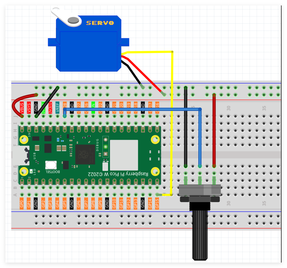
Servo motor control signal interfaces with GPIO pin GP13.
Potentiometer analog output connects to GPIO pin GP26.
Programming Implementation
Note
Follow the visual programming guide below using drag-and-drop techniques.
Load
2.7_Potentiometer_Control_Servo.pngfrom the directoryUltimate-Starter-Kit-for-Pico-W\Piper_Make. For comprehensive guidance, see Loading Existing Projects.
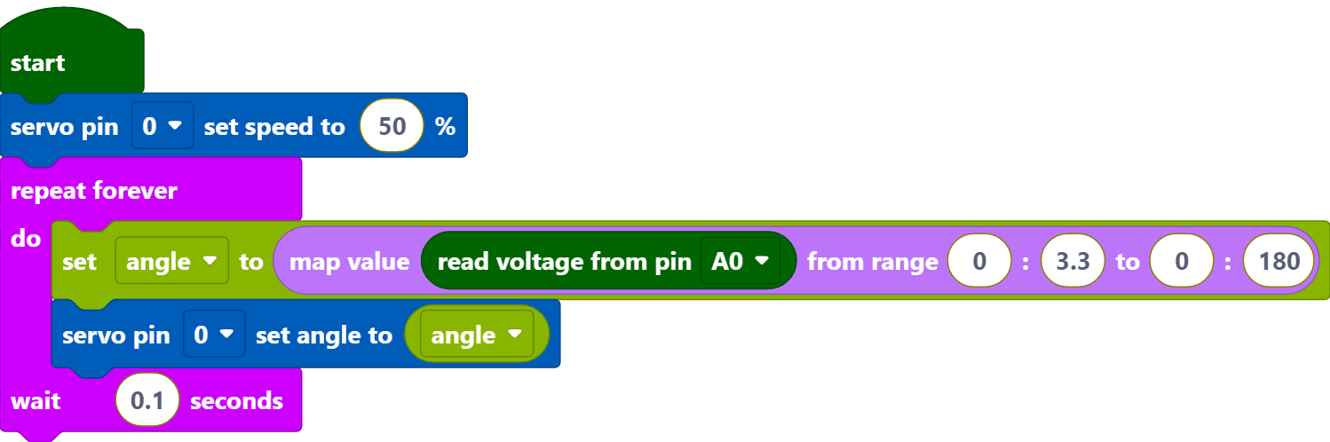
Upon Pico W connection, press the Start button to begin program execution. Adjust the potentiometer knob to control servo motor angular positioning in real-time.
How it Works?

Set the rotation speed of pin15 (servo) to 15%.
[servo pin() set speed to ()%]: Used to set the rotation speed of the servo pin, the range is 0%~100%.
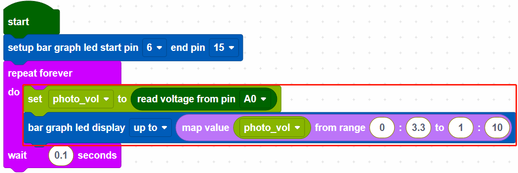
Create a variable [angle], then read the voltage of A0. Use the [map value () from () to ()] block, map the voltage of A0 from 0 to 3.3V voltage range to 0 to 180°, and then use the mapped angle as the rotation angle of the servo.
[map value () from () to ()]: map a value from one range to another.
Note
The voltage of A0~A2 takes the range of 0~3.3V, even if your power supply is connected to VBUS (5V).