2.4 RGB Color Blending System
This project demonstrates color manipulation using three potentiometers to control an RGB LED’s color output through variable resistance adjustments.
RGB LEDs integrate red, green, and blue light-emitting elements. Through proportional mixing of these primary colors, an extensive spectrum of colors becomes achievable.
Required Components
Raspberry Pi Pico W x1
MicroUSB cable x1
830 Tie-Points Breadboard x1
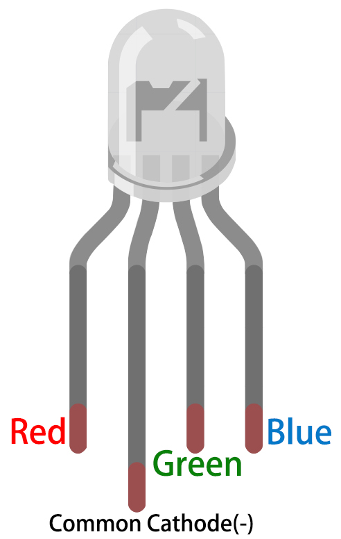
RGB LED x1
Potentiometer 10KΩ x3
Resistor 220Ω x3
Jumper Wire Several
Circuit Assembly
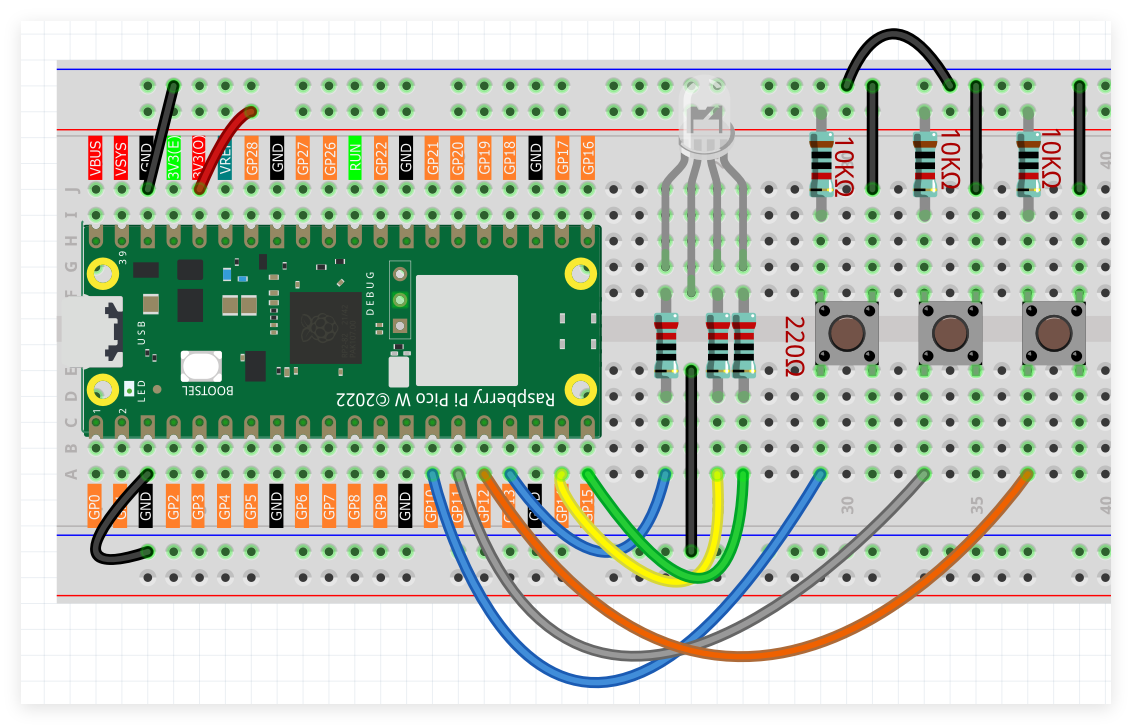
The RGB LED features four terminals: the extended pin serves as the common cathode (ground), while the remaining three pins function as anodes (positive terminals) for red, green, and blue channels.
Three potentiometers interface with GPIO pins GP26, GP27, and GP28 respectively.
RGB LED color channels connect to GPIO pins GP13, GP14, and GP15 correspondingly.
Programming Implementation
Note
Utilize the visual programming interface shown below through drag-and-drop methodology.
Import
2.4_RGB_Color_Mixing.pngfrom the locationUltimate-Starter-Kit-for-Pico-W\Piper_Make. For complete instructions, reference Loading Existing Projects.
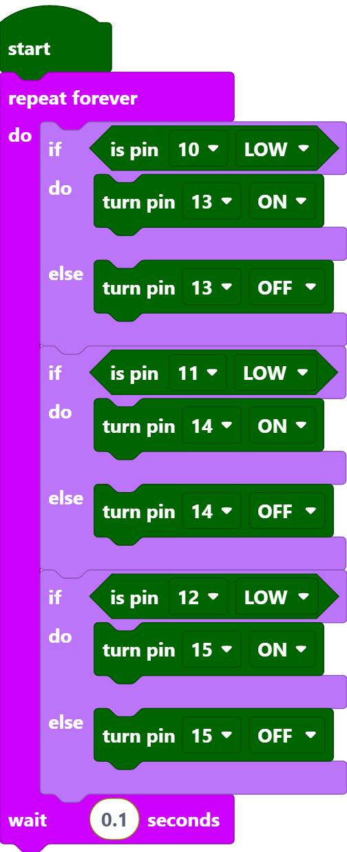
Following Pico W connection, activate the Start button to initiate program execution. Adjust the three potentiometers to manipulate RGB LED color output across the visible spectrum.