2.1 LED Blinking Fundamentals
In this tutorial, we’ll create a flashing LED circuit using external components. For beginners working with electronic modules, a prototyping breadboard serves as an essential tool for circuit construction.
A breadboard consists of a plastic base featuring numerous connection points arranged in a grid pattern. These connection holes enable quick insertion of electronic parts and facilitate circuit assembly. Since components aren’t permanently soldered, breadboards offer flexibility for circuit modifications and troubleshooting when errors occur.
Required Components
Raspberry Pi Pico W x1
MicroUSB cable x1
830 Tie-Points Breadboard x1
LED x1
Resistor 220Ω x1
Jumper Wire Several
Circuit Assembly
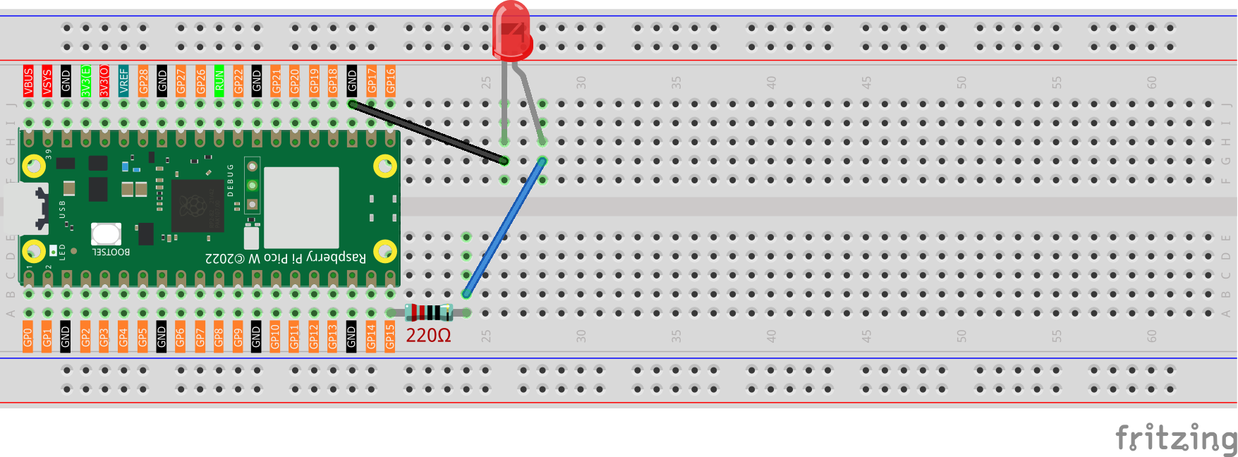
The 220-ohm resistor displays color bands: red, red, black, black, and brown.
LED polarity: the extended leg represents the positive terminal (anode), while the shorter leg is the negative terminal (cathode).
Programming
Note
Reference the visual guide below for drag-and-drop programming.
Load
2.1_Hello_Led.pngfrom the directoryUltimate-Starter-Kit-for-Pico-W\Piper_Make. For comprehensive instructions, see Loading Existing Projects.
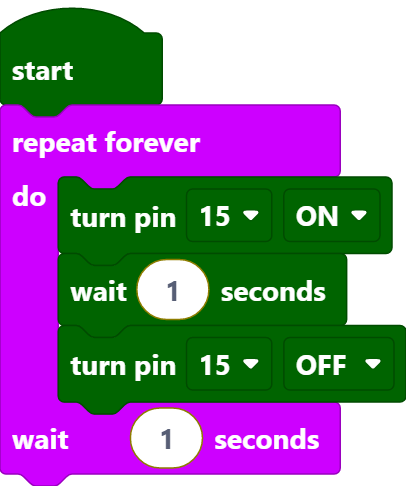
Once the Pico W is connected, press the Start button to observe the LED flashing pattern. For additional guidance, consult 1.2 Comprehensive Piper Make Walkthrough.
Operation Principles
The program loop operates as follows: activate pin15 to illuminate the LED, pause for one second, deactivate pin15 to extinguish the LED. After another one-second delay, the sequence repeats, creating a continuous on-off pattern.
[start]: This component establishes the program foundation and marks the execution starting point.
[repeat forever do() wait()seconds]: Creates an infinite loop where enclosed blocks execute continuously with user-defined timing intervals.
[turn pin () ON/OFF]: Controls pin state by setting it to high voltage (ON) or low voltage (OFF).
[wait () seconds]: Establishes timing delays between block executions.