2.3 Electronic Doorbell System
This project constructs an electronic doorbell using a microswitch and active buzzer combination. Pressing the switch triggers audible notification.
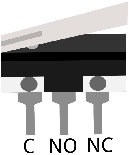
The microswitch features three terminals with specific designations: C (common terminal), NO (normally open contact), and NC (normally closed contact).
In the default state, terminals 1 (C) and 3 (NC) maintain electrical continuity, while activation connects terminals 1 (C) and 2 (NO).
Required Components
Raspberry Pi Pico W x1
MicroUSB cable x1
830 Tie-Points Breadboard x1
Micro Switch x1
Transistor S8050 x1
Active Buzzer x1
Resistor 1KΩ x1
Resistor 10KΩ x1
Capacitor 104 x1
Jumper Wire Several
Circuit Configuration
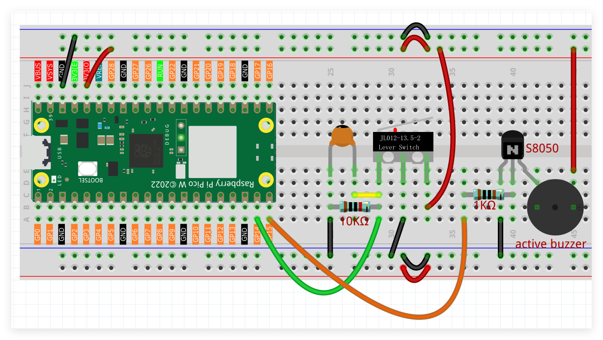
In the resting position, microswitch terminals 1 and 3 form a closed circuit, maintaining GP14 at low potential. Switch activation establishes GP14 high state.
GP15 generates high output signal to activate buzzer operation.
Programming Code
Note
Follow the visual programming guide below using drag-and-drop techniques.
Load
2.3_Door_Bell.pngfrom the directoryUltimate-Starter-Kit-for-Pico-W\Piper_Make. For comprehensive guidance, see Loading Existing Projects.
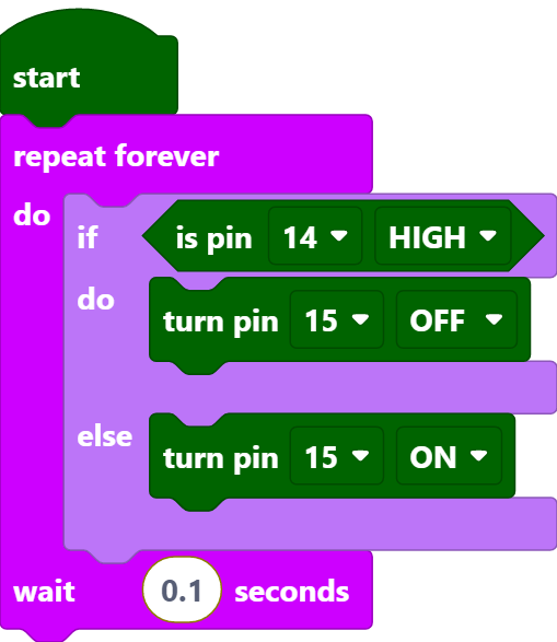
Upon Pico W connection, press the Start button to begin program execution. Switch activation produces audible buzzer output.