4.4 LED Dot Matrix
The LED matrix is a low-resolution dot-matrix display that uses an array of light-emitting diodes (LEDs) as pixels to create patterned displays. These matrices are bright enough to be visible even in outdoor sunlight and are commonly seen in stores, billboards, signs, and variable message displays (such as those on public transit vehicles).
The LED matrix used in this kit is an 8x8 dot matrix with 16 pins. The anodes of the LEDs are connected in rows, while the cathodes are connected in columns (at the circuit level). This configuration allows control over the 64 individual LEDs.
To light up the first LED, you need to provide a high level to Row 1 and a low level to Column 1. To light up the second LED, you would provide a high level to Row 1 and a low level to Column 2, and so on. By controlling the current through each pair of rows and columns, each LED can be individually controlled to display characters or images.
Component List
Raspberry Pi Pico W x1
MicroUSB cable x1
830 Tie-Points Breadboard x1
LED Dot Matrix x1
74HC595 x2
Jumper Wire Several
Component knowledge
LED Dot Matrix
The 8x8 dot matrix is controlled by two 74HC595 chips: one for the rows and one for the columns. These two chips share pins G18 to G20, which significantly reduces the number of I/O ports required on the Pico W board.
To display a pattern, the Pico W outputs a 16-bit binary number. The first 8 bits are sent to the 74HC595 controlling the rows, while the last 8 bits are sent to the 74HC595 controlling the columns.
The Q7’ pin is a series output pin, which can be connected to the DS pin of another 74HC595 to daisy-chain multiple 74HC595 chips together.
Connect
Build the circuit. Since the wiring is complicated, let’s make it step by step.
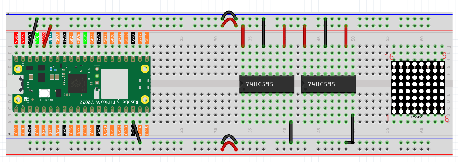
Step 1: First, insert the Pico W, the LED dot matrix and two 74HC595 chips into breadboard. Connect the 3.3V and GND of the Pico W to holes on the two sides of the board, then hook up pin16 and 10 of the two 74HC595 chips to VCC, pin 13 and pin 8 to GND.
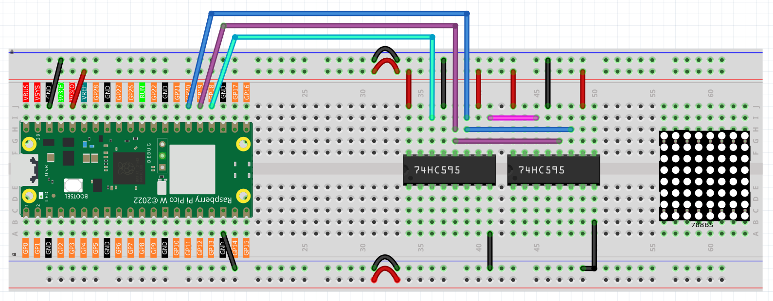
Step 2: Connect pin 11 of the two 74HC595 together, and then to GP20; then pin 12 of the two chips, and to GP19; next, pin 14 of the 74HC595 on the left side to GP18 and pin 9 to pin 14 of the second 74HC595.
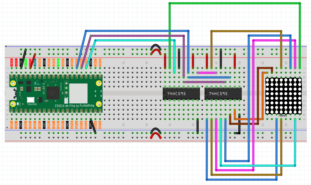
Step 3: The 74HC595 on the right side is to control columns of the LED dot matrix. See the table below for the mapping. Therefore, Q0-Q7 pins of the 74HC595 are mapped with pin 13, 3, 4, 10, 6, 11, 15, and 16 respectively.
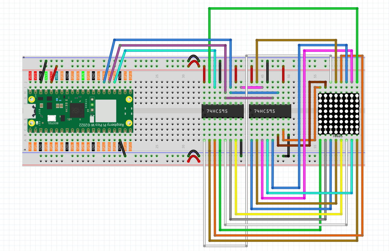
Step 4: Now connect the ROWs of the LED dot matrix. The 74HC595 on the left controls ROW of the LED dot matrix. See the table below for the mapping. We can see, Q0-Q7 of the 74HC595 on the left are mapped with pin 9, 14, 8, 12, 1, 7, 2, and 5 respectively.
Code
Note
Open the
4.4_led_dot_matrix.inofile under the path ofUltimate-Starter-Kit-for-Pico-W\Arduino\1.Projector copy this code into Thonny, then click “Run Current Script” or simply press F5 to run it.Or copy this code into Arduino IDE.
Don’t forget to select the board(Raspberry Pi Pico) and the correct port before clicking the Upload button.
Click “Run current script”, you will see a x graphic displayed on the 8x8 dot matrix.
The following is the program code:
// Define pins
const int SDI_PIN = 18;   // Data input
const int RCLK_PIN = 19;  // Storage register clock
const int SRCLK_PIN = 20; // Shift register clock

// Define pattern arrays
const byte hi_pattern[] = {
    0xFF, // 11111111
    0xAD, // 10101101
    0xAD, // 10101101
    0xA1, // 10100001
    0xAD, // 10101101
    0xAD, // 10101101
    0xFF, // 11111111
    0xFF  // 11111111
};

const byte music_note[] = {
    0xFF, // 11111111
    0xFF, // 11110111
    0xF1, // 11110001
    0xF3, // 11110011
    0xF7, // 11110111
    0xF7, // 11110111
    0xF7, // 11110111
    0xFF  // 11111111
};

const byte smile[] = {
    0xFF, // 11111111
    0xFF, // 11111111
    0xC3, // 11000011
    0xBD, // 10111101
    0xFF, // 11111111
    0x93, // 10010011
    0x93, // 10010011
    0xFF  // 11111111
};

const byte arrow_right[] = {0xFF,0xF7,0xFB,0x81,0xFB,0xF7,0xFF,0xFF};
const byte arrow_left[] = {0xFF,0xEF,0xDF,0x81,0xDF,0xEF,0xFF,0xFF};

void setup() {
  pinMode(SDI_PIN, OUTPUT);
  pinMode(RCLK_PIN, OUTPUT);
  pinMode(SRCLK_PIN, OUTPUT);
}

// Send data to 74HC595
void hc595_in(byte dat) {
  for (int bit = 7; bit >= 0; bit--) {
    digitalWrite(SRCLK_PIN, LOW);
    digitalWrite(SDI_PIN, (dat >> bit) & 0x01);
    digitalWrite(SRCLK_PIN, HIGH);
  }
}

// Output data to storage register
void hc595_out() {
  digitalWrite(RCLK_PIN, HIGH);
  digitalWrite(RCLK_PIN, LOW);
}

// Display pattern
void display_pattern(const byte pattern[], unsigned long duration_ms) {
  unsigned long start_time = millis();
  while (millis() - start_time < duration_ms) {
    for (int i = 0; i < 8; i++) {
      hc595_in(pattern[i]);
      hc595_in(0x80 >> i);
      hc595_out();
      delayMicroseconds(500);
    }
  }
}

// Scroll pattern to the left
void scroll_pattern_left(byte result[], const byte pattern[]) {
  for (int i = 0; i < 8; i++) {
    result[i] = ((pattern[i] << 1) | (pattern[i] >> 7)) & 0xFF;
  }
}

// Scroll pattern to the right
void scroll_pattern_right(byte result[], const byte pattern[]) {
  for (int i = 0; i < 8; i++) {
    result[i] = ((pattern[i] >> 1) | (pattern[i] << 7)) & 0xFF;
  }
}

// Scroll animation
void scroll_animation(const byte pattern[], char direction, int steps, int step_delay) {
  byte current[8];
  memcpy(current, pattern, 8);

  for (int step = 0; step < steps; step++) {
    display_pattern(current, step_delay);
    byte temp[8];
    if (direction == 'l') {
      scroll_pattern_left(temp, current);
    } else {
      scroll_pattern_right(temp, current);
    }
    memcpy(current, temp, 8);
  }
}

void loop() {
  // Display "HI" pattern
  display_pattern(hi_pattern, 1500);

  // Display music note pattern and scroll
  display_pattern(music_note, 1000);
  scroll_animation(music_note, 'l', 8, 150);
  scroll_animation(music_note, 'r', 8, 150);

  // Display smiley face
  display_pattern(smile, 1500);

  // Display arrow animation
  for (int i = 0; i < 2; i++) {
    display_pattern(arrow_right, 400);
    display_pattern(arrow_left, 400);
  }
}