4.2 7-Segment Display
Welcome to the world of 7-segment displays - those classic digital digits you see everywhere! From digital clocks to calculators, microwave timers to elevator floors, these displays create numbers in that familiar “digital font” we all recognize.
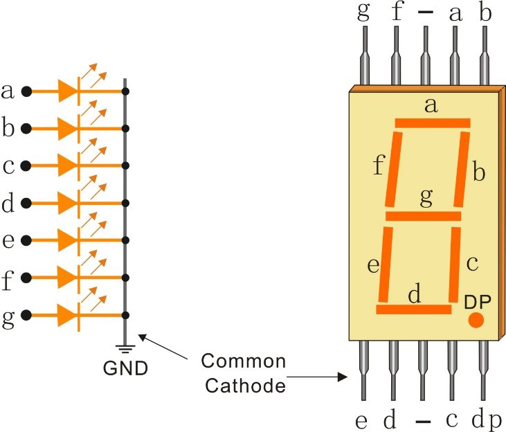
What’s inside: It’s actually 8 individual LEDs cleverly arranged: - 7 segments (labeled a, b, c, d, e, f, g) form the “8” shape - 1 decimal point (dp) for numbers like “3.14”
The pin layout is illustrated in the figure below.
The challenge: Controlling 8 LEDs normally needs 8 GPIO pins! But with our 74HC595 from the previous lesson, we can control all segments using just 3 pins. Smart engineering!
Component List
Raspberry Pi Pico W x1
MicroUSB cable x1
830 Tie-Points Breadboard x1
7-segment Display x1
Resistor 220Ω x1
74HC595 x1
Jumper Wire Several
Component knowledge
7-segment Display
How we create numbers:
Pattern Magic: - Each digit (0-9, A-F) has a unique LED segment pattern - Example: “8” = all 7 segments ON, “1” = only segments b+c ON - We store these patterns as binary codes and send them to the 74HC595
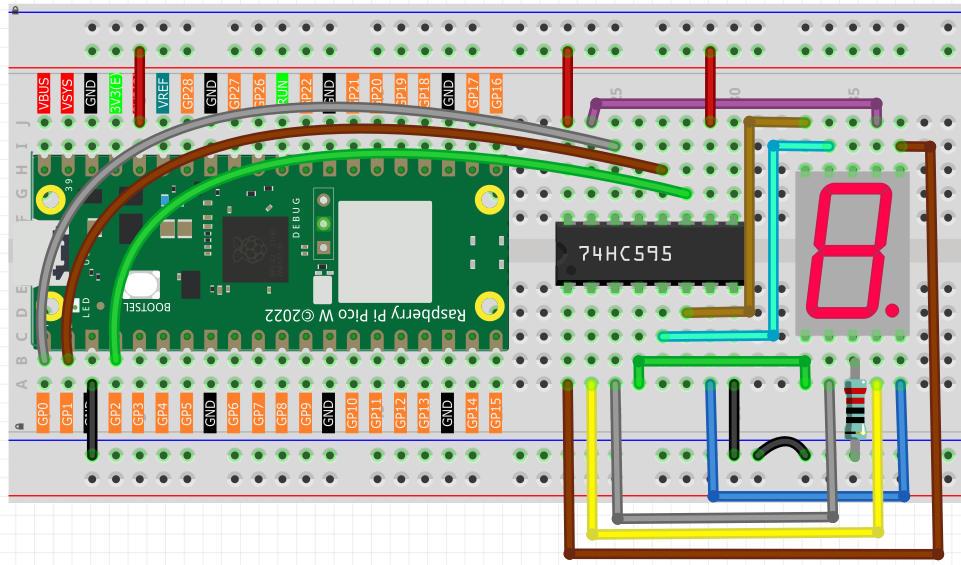
Same 74HC595 setup as before, but now the 8 outputs connect to the display segments instead of individual LEDs.
Connect
Code
Note
Open the
4.2_7_segment_display.inofile under the path ofUltimate-Starter-Kit-for-Pico-W\Arduino\1.Projector copy this code into Thonny, then click “Run Current Script” or simply press F5 to run it.Or copy this code into Arduino IDE.
Don’t forget to select the board(Raspberry Pi Pico) and the correct port before clicking the Upload button.
After running the code, watch your 7-segment display count through all hexadecimal digits (0-9, A-F)! Each digit appears for about 0.8 seconds, showing how different segment combinations create recognizable numbers and letters. It’s like watching a tiny digital counter in action!
The following is the program code:
/*
 * 7-Segment Hexadecimal Display Project
 *
 * Displays hexadecimal digits 0-F on a 7-segment display using
 * a 74HC595 shift register. Cycles through all 16 hex digits
 * continuously for educational and debugging purposes.
 *
 * Hardware: 74HC595 shift register + Common Cathode 7-segment display
 */

// 74HC595 Pin Configuration Constants
#define LATCH_PIN             1     // ST_CP (Storage Register Clock) - pin 12 of 74HC595
#define CLOCK_PIN             2     // SH_CP (Shift Register Clock) - pin 11 of 74HC595
#define DATA_PIN              0     // DS (Serial Data Input) - pin 14 of 74HC595

// Display Timing Constants
#define DIGIT_DISPLAY_MS      800   // Time to display each digit (milliseconds)

// 7-Segment Display Patterns for Hexadecimal Digits (0-F)
// Pattern format: gfedcba (bit 7 unused, bits 6-0 control segments)
byte hexDigitPatterns[] = {
  0x3F,  // 0: segments a,b,c,d,e,f
  0x06,  // 1: segments b,c
  0x5B,  // 2: segments a,b,d,e,g
  0x4F,  // 3: segments a,b,c,d,g
  0x66,  // 4: segments b,c,f,g
  0x6D,  // 5: segments a,c,d,f,g
  0x7D,  // 6: segments a,c,d,e,f,g
  0x07,  // 7: segments a,b,c
  0x7F,  // 8: segments a,b,c,d,e,f,g
  0x6F,  // 9: segments a,b,c,d,f,g
  0x77,  // A: segments a,b,c,e,f,g
  0x7C,  // b: segments c,d,e,f,g
  0x39,  // C: segments a,d,e,f
  0x5E,  // d: segments b,c,d,e,g
  0x79,  // E: segments a,d,e,f,g
  0x71   // F: segments a,e,f,g
};

/**
 * Arduino Setup Function
 * Initializes the 74HC595 control pins as outputs.
 */
void setup() {
  pinMode(LATCH_PIN, OUTPUT);
  pinMode(CLOCK_PIN, OUTPUT);
  pinMode(DATA_PIN, OUTPUT);

  // Clear display initially
  updateDisplay(0x00);
}

/**
 * Arduino Main Loop Function
 * Continuously cycles through hexadecimal digits 0-F.
 */
void loop() {
  displayHexadecimalSequence();
}

/**
 * Update Display
 * Sends pattern data to 74HC595 and updates the 7-segment display.
 */
void updateDisplay(byte pattern) {
  digitalWrite(LATCH_PIN, LOW);                    // Prepare for data transmission
  shiftOut(DATA_PIN, CLOCK_PIN, MSBFIRST, pattern); // Send 8-bit pattern
  digitalWrite(LATCH_PIN, HIGH);                   // Latch data to display
}

/**
 * Display Hexadecimal Sequence
 * Cycles through all hexadecimal digits 0-F with appropriate timing.
 */
void displayHexadecimalSequence() {
  for (int digitIndex = 0; digitIndex < 16; digitIndex++) {
    updateDisplay(hexDigitPatterns[digitIndex]);
    delay(DIGIT_DISPLAY_MS);
  }
}